
How Automatic Condenser Tube Cleaning Works
A simple, continuous cycle that keeps every condenser tube clean while the plant runs — no chemicals, no shutdowns, no manual brushing.
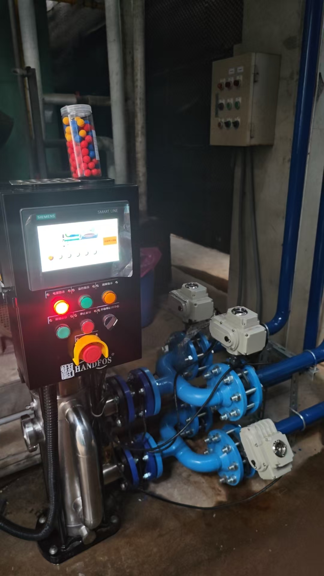
The PLC controller schedules and monitors every cleaning cycle.
The 4-Step Cleaning Cycle
Inject
The PLC signals the injection pump to feed balls into the condenser inlet water box.
Pass
Cooling water carries balls through every tube. Slightly oversized balls wipe the inner wall.
Collect
A ball trap at the outlet recovers balls while letting cleaned water continue to the cooling tower.
Return
Balls are returned to the injection reservoir and the cycle repeats automatically.
System Components & Their Roles
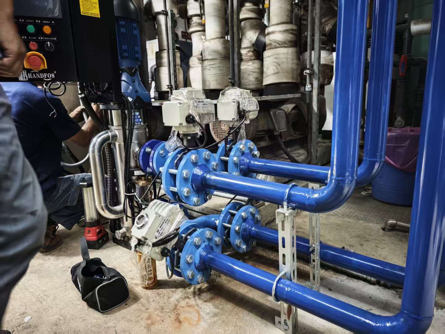
Ball collection piping with motorized isolation valves.
- Ball injection pump / hopper — feeds the correct ball count into the condenser inlet.
- Ball collector / strainer — separates balls from outlet flow and sends them back.
- Motorized valves — direct water flow between normal operation and cleaning mode.
- PLC + HMI panel — sets schedules, monitors cycles and reports alarms to BMS.
- Sponge rubber balls — the cleaning medium, sized to each tube ID.
Why Continuous Cleaning Beats Periodic Cleaning
Manual or chemical cleaning removes fouling only after performance has already dropped. By the time you notice higher power bills, tubes may already have permanent pitting or scale. ATCS prevents fouling from accumulating in the first place, so heat-transfer surfaces stay at design condition every hour of every day.
Frequently Asked Questions
Get a Free ATCS Sizing Quote
Tell us your chiller / condenser model, cooling capacity and water quality. We reply within 24 hours with a tailored solution and ROI estimate.
Prefer email? Write to michealzhang969@gmail.com