
ATCS for District Cooling Plants
District cooling plants run flat out for months in hot climates. Fouled condenser tubes force chillers to draw more power just when cooling demand is highest, inflating operating costs and carbon intensity.
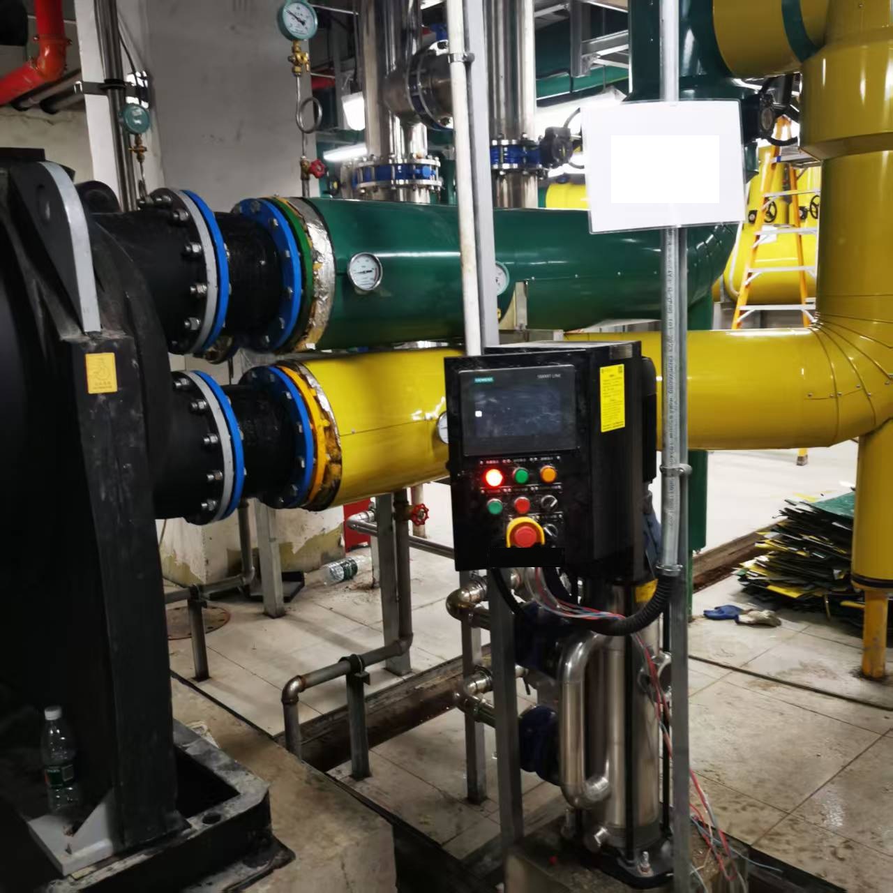
Key Benefits for District Cooling
Cut kW/ton Through the Season
Clean tubes keep chiller lift low and efficiency high all summer.
Avoid Capacity Shortfalls
Deliver contracted cooling capacity even during heat waves.
Reduce Chemical Use
Less need for biocide and descaling chemicals in cooling water.
Remote Monitoring Ready
BMS integration lets the central operations team see every chiller.
Typical System Configuration
District cooling skids serve multiple chillers from one ball management station or independent skids per chiller. Collectors are sized for constant-speed or variable-primary flow, with ball counters and loss alarms.
| Item | Specification |
|---|---|
| Applicable tube ID | 12 – 30 mm (custom up to 45 mm) |
| Ball material | EPDM, oil and seawater resistant |
| Collector material | Carbon steel / 316L SS / Duplex SS |
| Control | Siemens PLC, Modbus/BACnet to BMS |
| Communication | Remote monitoring and alarm feedback |
Frequently Asked Questions
Why District Cooling Feels Fouling Differently
A district cooling plant is not simply a large chiller plant. It is a production facility whose output is measured in tonnes of chilled water delivered to a network that was sized for peak demand. That difference changes what condenser fouling actually costs.
In a commercial building, a few percent of condenser capacity lost in August means slightly higher electricity consumption. In a district cooling plant during peak season, the same few percent can mean the difference between meeting the network load and not meeting it — because the distribution network has no spare margin to absorb the shortfall. Capacity, not energy, is the binding constraint.
High ambient conditions make this worse. Gulf plants operate with elevated wet-bulb temperatures for months, which limits how low the cooling tower can push condenser water. Every degree of approach temperature lost to fouling is a degree the plant cannot recover elsewhere in the cycle — the thermal margin is already spent on the climate.
There is also an amplification effect. District plants run multiple large machines in parallel, and a fouled condenser on one unit changes how that unit loads relative to its neighbours. Operators end up running more machines at part load to meet the same demand, which pushes the plant away from its best efficiency point — a second penalty layered on the first.
Parameters We Need for a District Cooling Proposal
These are the values that determine equipment sizing and the payback estimate.
| Parameter | Why it matters | Typical range |
|---|---|---|
| Plant capacity (TR) | Sizing the cleaning loop and ball inventory | 10,000 – 100,000+ TR |
| Design wet-bulb | Sets achievable condenser water temperature | 26–32°C (Gulf) |
| Annual operating hours | Converts the efficiency gain into annual kWh | 5,000 – 8,760 h |
| Make-up water source | Determines scaling and biological risk | Municipal / brackish / seawater |
| Current approach temperature | The single best measure of recoverable loss | Clean 0.8–1.7 K |
District Cooling Questions
How is this different from cleaning a commercial building chiller?
The physics is identical; the consequence is not. In a district plant the machines feed a shared network with peak-sized capacity, so a capacity loss threatens service rather than just raising the power bill. Sizing also has to account for parallel-machine loading effects, and the cleaning system must operate across the full turndown range as machines stage on and off.
Can cleaning continue during peak season?
Yes — that is precisely the point. Cleaning runs while the machine is in service, so you do not have to choose between cleaning a condenser and serving the network in August. Ball replacement and screen inspection are performed on the running system without interrupting chilled water production.
Do we need one system per chiller?
Generally yes for the injection and collection equipment, since it is installed on each condenser’s water circuit. Control panels can often be common or integrated into the plant DCS, so operator workload does not scale linearly with machine count. We confirm the arrangement once we see the plant layout and condenser piping.
Will this interact with the network hydraulic balance?
No, provided the installation is correctly sized. The cleaning loop introduces a small, constant pressure drop that is accounted for at design stage; it does not modulate with network demand and does not affect distribution pumping or differential pressure control. We provide the pressure drop figure in the proposal so your hydraulic model can be updated.
ATCS for District Cooling: Protecting Central-Plant Efficiency
District cooling distributes chilled water from a central plant to many buildings, so the central chillers operate at very large capacity and often run seasonally. Because a district-cooling plant serves a whole district, even a small drop in chiller efficiency multiplies across an enormous energy volume. An Automatic Tube Cleaning System (ATCS) keeps the central plant’s condenser tubes clean, safeguarding the plant’s design COP across the entire cooling season.
How ATCS Works in District Cooling — 4 Steps
- Plant-scale cleaning: each large central chiller condenser is fitted with an ATCS ball system sized for high flow.
- Seasonal duty: unlike small sites, district plants run for months continuously; ATCS operates unattended the whole season.
- Free-cooling synergy: clean condensers let the plant exploit low-ambient and free-cooling windows at maximum efficiency.
- Central monitoring: skids report to plant SCADA with ball-count and flow-health alarms.
ATCS vs. Traditional Central-Plant Cleaning
| Method | How It Works | Downtime | Efficiency Outcome | Best For |
|---|---|---|---|---|
| Manual condenser clean | Shut plant, brush / acid | High (plant stop) | Restored periodically | Backup only |
| Chemical treatment | Continuous / biocide dosing | Low | Slow drift | Supplementary |
| ATCS (this system) | Automated continuous ball cycle | Zero | Sustained design COP | Large central plants |
Key Technical Parameters
| Typical Specification Range | |
| Condenser scale | Single / multi-chiller, up to large central units |
| Tube Ø | 16–32 mm |
| Cycle interval | 20–40 min |
| Ball grade | 40–70 Shore A (sponge rubber) |
| Integration | SCADA / BMS |
| Ball life | 6–18 months |
Why Choose ATCS for District Cooling?
- Scales with the plant — one clean-condenser policy across all central chillers.
- Maximizes free-cooling — clean surfaces capture every low-temperature opportunity.
- Cuts district energy cost — a few % COP gain equals massive kWh at plant scale.
- Reliability — unattended whole-season operation, alarms on deviation.
Get a District Cooling ATCS Quote
Tell us your chiller / condenser model, cooling capacity and water quality. We reply within 24 hours with a tailored solution and ROI estimate.
Prefer email? Write to michealzhang969@gmail.com
Related Verified Case Studies
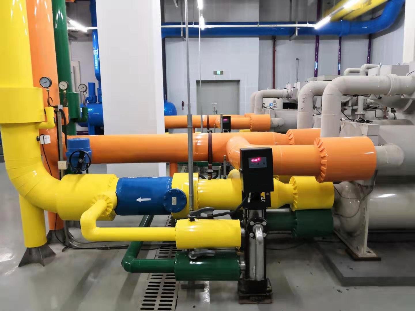
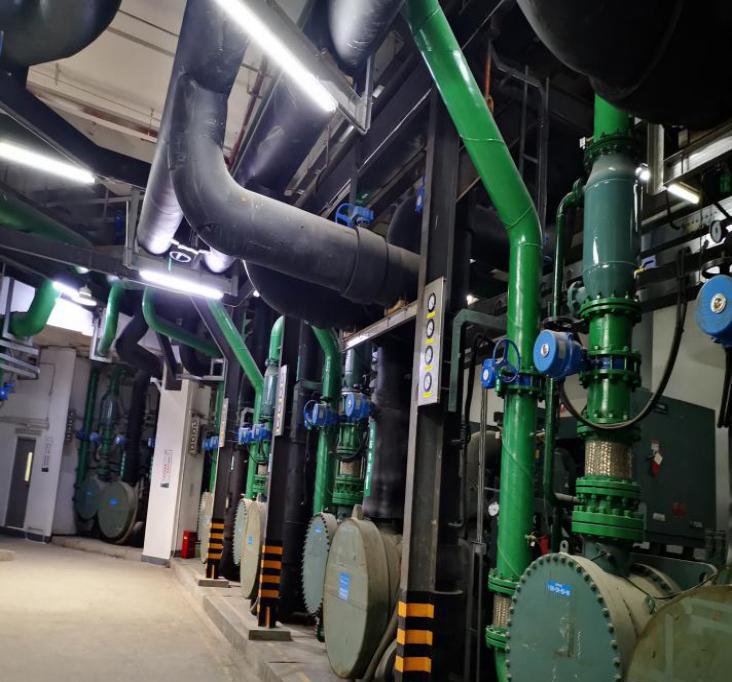
See the HyApexFlow automatic condenser tube cleaning system (ATCS) proven in the field:
Explore more in our Automatic Condenser Tube Cleaning (ATCS) →